 If you buy a new computer motherboard it usually comes with an user manual. There you should be able to find the front panel header pinout information for the motherboard, sometimes the pinout diagram is printed on the motherboard too. But you may have trouble when changing the computer’s casing if you lost the manual and the pinout information is nowhere to be found on the board. Not all motherboards use the same front panel header pinout, you can search the Internet but it may be hard to find the correct pinout information if the motherboard is not a common model. I had such bad experience so I wrote this post for all the front panel connector diagrams that I ever used.
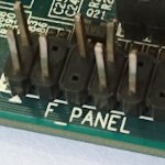
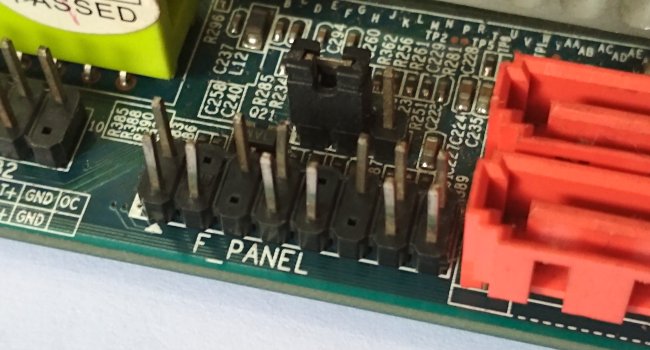
Computer front panel header is where the connectors of casing cables (reset button, power on/off button, power on light and hard disk activity light) and the motherboard are connected. Sometimes it includes speaker connector. But front USB, front audio, card reader are not included in this header because they have their own connectors.
Front panel header has many names:
- Front Panel Connector
- F_Panel
- JPanel
- JFP1
Computer front panel usually has these pins:
- POWER or POWER SW or ON/OFF
- RESET or RESET SW or RST
- MSG or POWER LED or POW LED or PLED
- HDD or HDD LED or HLED
- SPEAKER or SPK
- CI (chasis intrusion)
- +5V or NC (not connected) or RSVD (reserved) or DUMMY
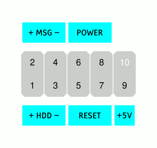
On the diagrams below, the white text numbers mean there is no pin on the position.
Front Panel 10 Pin | Some Call It 9 (or 10 – 1) Pin
This is the most commonly used pinout.
Motherboards that use this model front panel pinout are:
AFOX IH81-MA2-V2, ASRock 775VM800, ASRock Wolfdale1333-D667, ASUS H81M-K, Asus P5KPL-AM SE, ECS G41T-M16
Front Panel 20 Pin | Some Call It 12 (or 20 – 8) Pin
Motherboards that use this model front panel pinout are:
Asus P5KPL/EPU, Asus P5Q-EM, Asus P5Q SE2
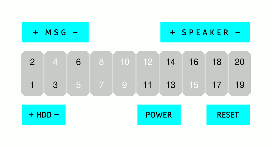
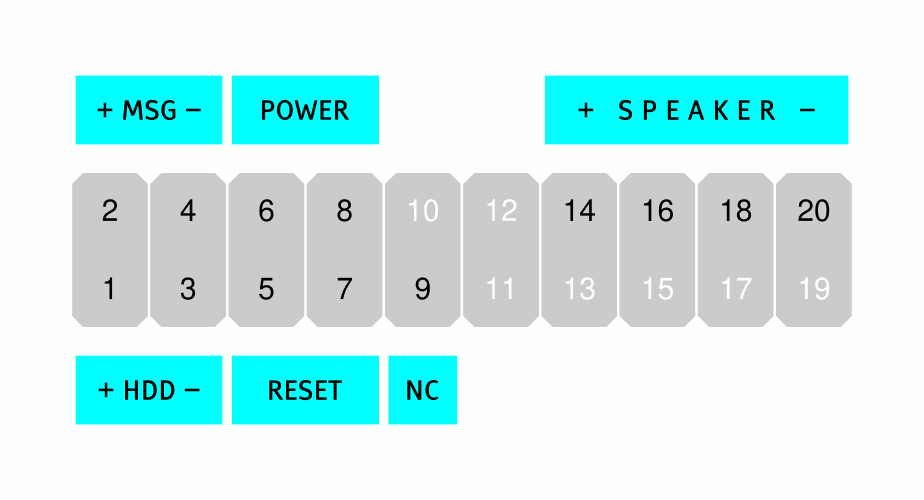
Front Panel 20 Pin | Some Call It 13 (or 20 – 7) Pin
It is similar to the 10 pin (10-1) diagram but this one has a speaker connector.
Motherboards that use this model front panel pinout are:
Gigabyte GA-EP35-DS3, Gigabyte GA-EP43-UD3L, Gigabyte GA-G31M-ES2L
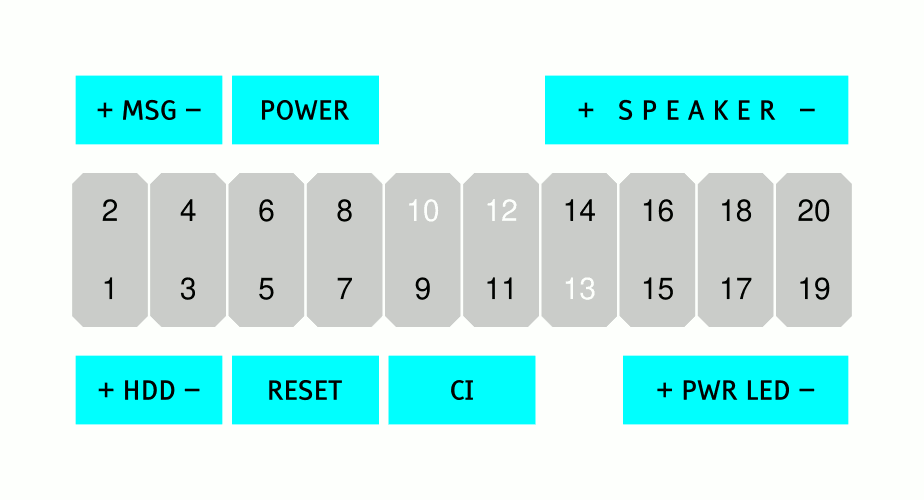
Front Panel 20 Pin | Some Call it 17 (or 20 – 3) Pin
This one has a CI connector and an additional LED for indication sleep mode.
Motherboards that use this model front panel pinout are:
Gigabyte GA-B85M-HD3-A, Gigabyte GA-G41M-Combo, Gigabyte GA-H61M-S2P
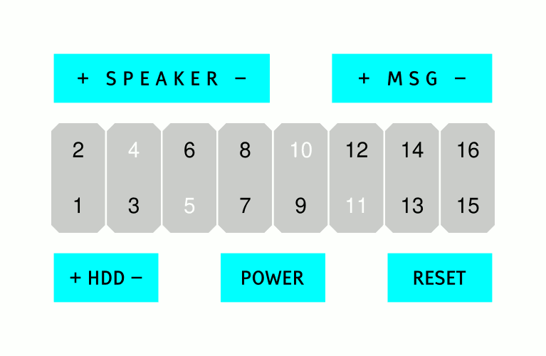
Front Panel 16 Pin | Some Call It 12 (or 16 – 4) Pin
The Power connector is on the center (pins 7 & 9).
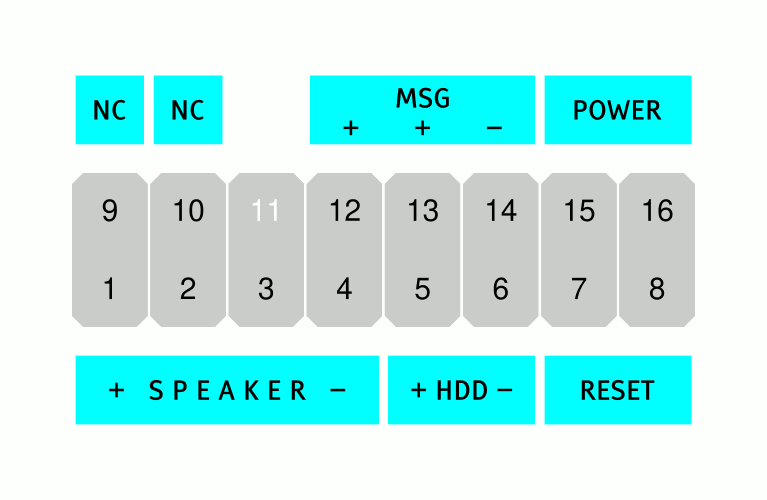
Front Panel 16 Pin | Some Call It 15 (or 16 – 1) Pins
Motherboards that use this model front panel pinout are:
Biostar A55MLV, Biostar A75MG, Biostar G31M, Biostar G41D3C, Biostar H61MU3B, Biostar P4M900-M7 FE
I was looking for a 25 pin